Mid term Project - The ScoPi M42 v0.3 Beta
ScoPi M42 v0.3 beta
Digiscoping made easy, fun,
full featured and open source!

Raspberry Pi and the PI Logo
are registered Trademarks of
the Raspberry PI Foundation
The
ScoPi M42 is intended to be a fully featured telescope/digiscope,
meant to do way with additional equipment such as expensive external
imagers for digiscoping or astrophotography. The advantage of the
system is that it can take interchangeable manual focus lenses of the
type M42 screw mount. In this mount there are several inexpensive
quality optics as well as some higher priced, higher quality optics,
from Carl Zeiss to Russian copies of German optics such as the MTO
1000mm f/10.
The ScoPi system takes
advantage of the small size sensor within the RaspiCam to increase
magnification of these optics (more on this later). In addition,
being a fully featured system, the user has at their disposal a fully
fledged PC with connectivity options, from WiFi,Ethernet, Bluetooth
and HDMI out, meaning that editing on location is possible (albeit
more comfortable using an external HDMI display) as well as the
capability to set it up as an IP camera.
Initially,
the ScoPi was being developed around another open source platform,
Arduino, with the aim of being an absolutely frugal digital imaging
device, but this presented its obstacles. At the present stage, the
ScoPi is a proof of concept and further development is needed, which
will be discussed below.
The
ScoPi concept was born out of my interest and specialist area in
Photography. Originally intended to be an absolutely frugal system of
imaging with telephoto photographic optics based around the Arduino
platform (in fact, originally the name was ScopeUino), the ScoPi took
a developmental turn to the concept that it is now. It was intended
mainly for astrophotography and birding, which usually require long
optics with small apertures and this is where the ScoPi shines, the
user can use a shorter optic with a bigger aperture or even a longer
optic with a relatively big aperture. As an example, the ScoPi’s
range with a 135mm f3.5 is the same as a lens nearly seven times
longer, by simply using the commonly known (in photographic circles)
crop factor related to sensor size, which is demonstrated below
(Fig.1). Lately webcam and small camera as well as camera phone
technology has advanced enough to produce acceptable and sometimes
outstanding results and this was in part driver for this project.
Many amateur astrophotographers for example, can nowadays use their
webcams to photograph the stars although with cumbersome equipment
attached.
Although small sensors have
the crop factor advantage for long range work, this is not without
it’s disadvantages; small sensors tend to be noisier, have less
dynamic range (the ability to pull detail out of highlight and shadow
areas alike, but particularly highlights) and if in a phone or
webcam, coupled to optics that are more often than not subpar and
fixed, among other issues.

Fig.1 Crop Factor
Crop
factor illustrated by Nasim Mansurov (Photography Life,
https://photographylife.com/what-is-crop-factor).
the Raspicam's sensor is below the scale here and therefore not represented
Having established that, the
RaspiCam sensor used in the ScoPi is considered to be among the best
out there for a webcam, offering a resolution of of up to 8MP stills
and 1080p Video, as well as some control over settings albeit over a
terminal. A dedicated GUI is possible and is being researched and
developed.
In addition, the ScoPi is a
fully integrated, portable system, made possible by being based on
the Raspberry Pi (model 3B), which means that you are not only
carrying a telescope and camera but also a PC with full capabilities.
The low power consumption of the Pi and it’s versatility with power
sources (in this case and Adafruit Powerboost is used), allows the
ScoPi to operate with as little as two AA batteries to a mobile phone
charger or powerpack.
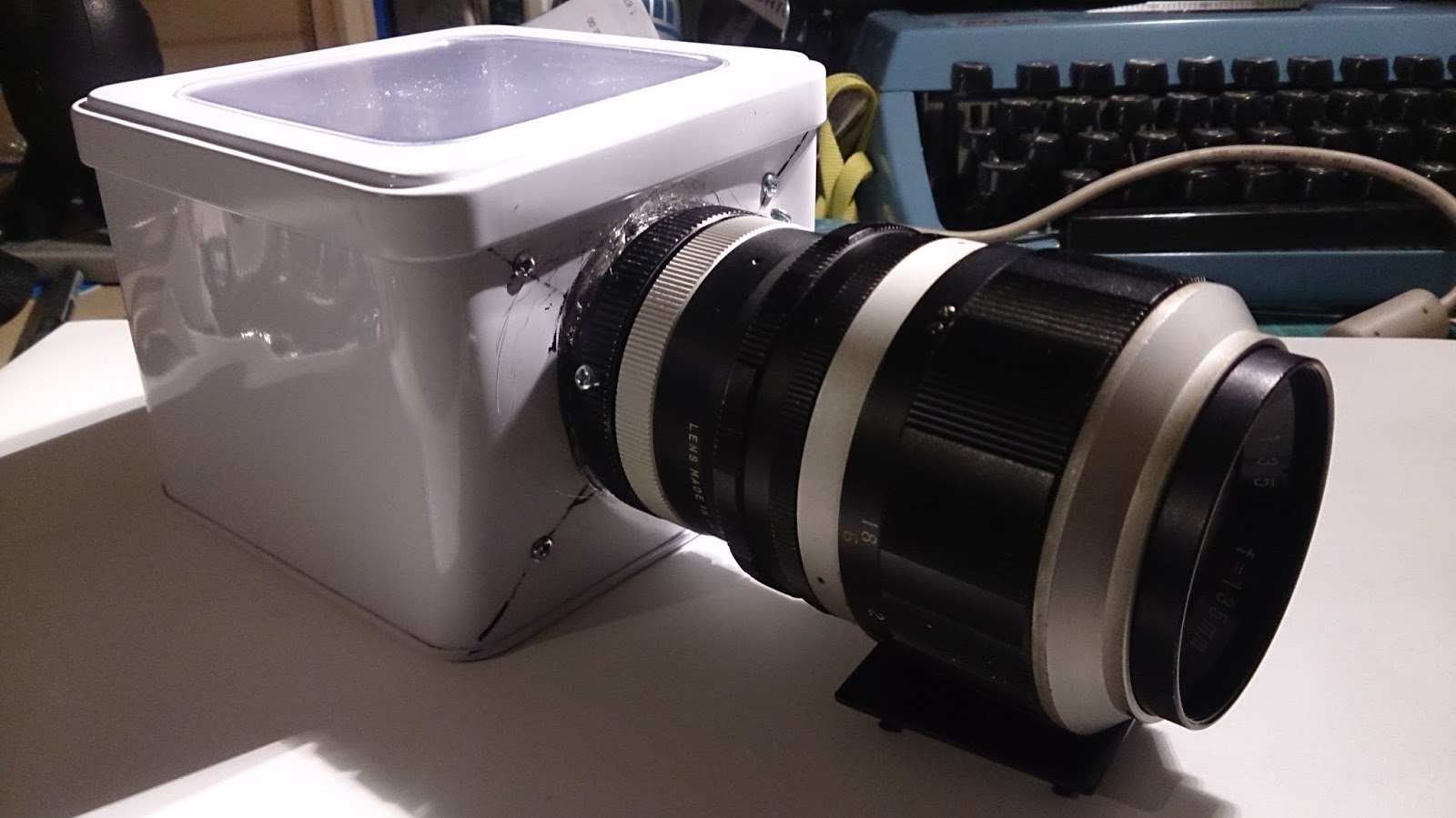
Although the project made a
jump from the frugal Arduino to the slightly less frugal Raspberry
Pi, in keeping with the spirit of frugality, the ScoPi was designed
around an underwear retail tin box. We will discuss the project, in
further detail below and go through the developmental journey of the
project.
As
previously discussed, the ScoPi was initially based around the
Arduino platform and it was intended to by a more frugal and a
somewhat less serious piece of equipment. While researching to build
the unit around the Arduino platform, several postings within the
online Arduino communities were skeptical of the platform’s ability
to produce video or stills but several more were positive, due to
recent developments in technology that would allow it. One example of
this, is the Arducam project (http://www.arducam.com/)
and the several imaging modules now available for the Arduino
platform albeit of lower resolution hitting the maximum resolution of
640x480 (VGA). For my initial intents and purposes this was fine at
the time; I had conducted preliminary primary research using the
imaging sensor from a PS3 Eye Toy camera coupled to an M42 optic with
excellent results within its limits in resolution. Furthermore, the
amount of control over parameters such as exposure, framerates
(although low), etc, looked promising. Researching within the Arduino
community, indicated at the time that this was all possible, albeit
with a little more coding and patience.


Wires galore! None of the
posts on the online community mentioned that the cameras required
separate purchase of connectors, as such I resorted to making my own
and with the only wire I had left and pair the connections
sequentially. Note the level shifters required for simple camera
operation on the Arduino (Luis Rubim, 2017)
With time beginning to be of
the essence and after going through 3 camera modules and 2 Arduino
platforms, it was too late to change the project which was also an
idea within my interests. It was soon clear that within that time
frame an Arduino based camera was out of my scope and as such I
ordered a Raspberry Pi, with a RaspiCam and a touchscreen. While this
seemed like the end of obstables and technical issues, it was far
from it. But first a look at how the physical object came to be.
Developing the ScoPi M42
0.3 Beta
The frugality of the project
was always a must. I enjoy changing ordinary day to day objects into
something special or different. I enjoy challenging myself and the
project gave me an opportunity to couple Physical Computing with my
interests.
At
the heart of the ScoPi is the imaging sensor of the RaspiCam. For it
to make use of the interchangeable lenses, it required modification.
The lens assembly had to be removed which required detaching the on
module cable. This is a fiddly operation as the sensor module is
attached to the camera module with simple adhesive, as such its easy
to throw it out of alignment. While I have no photos of this
delicated procedure, precisely for this reason, I would not be
controlling anything else or minding anything else during this
procedure: a bare sensor, particularly this diminutive is a
sensitive piece of electronics, to dust, electrostatic discharge,
sneezes, breathing over it, etc. There are walkthroughs online,
including how to turn the RaspiCam into an IR camera as well as
surveillance camera, but of note is Singleton Miller’s Wiki on how
to disassemble the camera (available at
http://wiki.raspberrytorte.com/index.php?title=Camera_Module_Lens_Modifcation#References).
But before this I needed to ensure that the system was working. The
stock Raspbian, recommended by the Raspberry Pi community is in fact
rather limiting and lagging in performance, compared to the one true
alternative, Ubuntu Mate. The stock Raspbian presented limitations
using its own brand RaspiCam and required considerable updates and
downloads to get it to work with any software other than terminal
command “raspistill” and options. It was missing UV4L drivers
which are required for a variety of webcams which are not of the USB
type but built in.
After, a few hours of
configuring it worked, but this was all being done on a TV screen. As
I then moved one to installing the touchscreen, further problems
started. The screen is not native and uses very specific drivers.
Upon first installation, it induce a kernel panic in the system and
hours of work were lost. At this point, I decided to restore the
system to Ubuntu Mate, due to Ubuntu’s known versatility and
compatibility with drivers. Once restored, the drivers were
installed, but the HDMI was disabled and made only accessible via a
terminal command.Installing the required drivers for the webcame with
a little coding on the terminal got the webcam working.With the clock
ticking, I finally had a working system to base the now materialising
ScoPi on.
The next step was to remove
the lens assembly as discussed above and find the register distance
for from the back element of the lens to the sensor. For this
purpose, I used black camera film cannisters (sensors like film
perform best in dark chambers) which I cut at different lengths, with
the sensor attached to the cap.


Top, the initial test
cannister as sensor chamber test. This distance was fine for the PS3
Eye Toy Camera sensor but not for the Raspicam’s. Bottom, where the
Raspicam’s sensor ended.Very close to the back of the lens by
comparison (Luis Rubim,2017).
Once the register distance was
found, it was time to test it. Upon first test, the images had a
strong green tint. For several hours I thought I had damaged the
sensor, or a cable was loose, or the cable was slightly broken. But
it turns out that the camera struggles, with stock software, to read
out white balance. But it was also at this stage that I found that
the imaging sensor itself is in fact defective and has a blemise
right at the center (or it could be around the center, since the
original lens sits right at the center so less care is taken on
surrounding areas). This is demonstrated in images that expose
correctly, with wild colour shifts and center balanced images (shown
later on the report). With not time or resources to order a new one,
I have carried on with the project, moving on to modifying the design
of the box. Below, the ScoPi throughout all of its iterations to the final stage.


Powering the ScoPi on the move
was made possible by using an Adafruit Powerboost and a micro-USB
cable connected to the Pi which is extendable and connects to the
Adafruit in the same way. Needless to say, this makes the ScoPi not
quite weatherproof yet, along with its visible ports. However,power
wise 2 AA batteries power the ScoPi but it can also be powered by a
standard mobile phone charger, or powerpack. A Li-ion system will be implemented in the future.


An insulated Adafruit,
connected to AA NiMh 2900mAh batteries, power the ScoPi. (Luis
Rubim,2017).
Below, the first subject shot with the ScoPi and a 135mm lens, usingCheese, the Linux Webcam App. Note the colour shifts, resulting from a factory blemished or damaged sensor or IR filter.

Videos of the ScoPi in action
In conclusion....
The ScoPi at this stage is
more of a concept than a finished product, but one that nonetheless I
enjoyed producing despite the setbacks, as I have enjoyed taking on
the challenges and problem solving. At this point I would perhaps
change the imaging sensor but perhaps just as important, given what
and who the ScoPi is targeted at, develop or find suitable Linux
software that allows further control of exposure settings which is of
the essence for Astrophotography for example. On a more holistic
note, I have found difficulty researching and understanding
information with the online open source community, both with Arduino
and Raspberry Pi, which puts into perspective why hacker meets and
events where community members meet in person are important. I had to
resort by and large to my own experience with open source software to
get around obstacles as well as my specialisation.
On a positive note, the ScoPi
bore out of failure to an extent and perseverance. It is a project I
will continue to work on but perhaps on an extra curricular basis.
Time constraints and other commitments also meant that the ScoPi was
produced by and large by hand at home, which presented its own
challenges, which I enjoyed and had to come up with inventive ways of
solving them.
Finally, does the ScoPi
accomplish as a concept what it’s meant to achieve?
From a personal and somewhat
specialist perspective yes, in many respects, but it potentially
could at this point achieve many aspects in full, if it weren’t for
resource limitations and setbacks, but nevertheless it is still a
bundle of fun. However it would be interesting to put it to the test
casually with a group of photography curious and physical computing
curious individuals. That would be a real test.
References
Articles/Wikis:
Mansurov, N. “What is
Crop Factor?”., 2017. Web. 23 Feb. 2017. (Available at
https://photographylife.com/what-is-crop-factor)
Miller,S.”Camera Module
Lens Modification”.2013,Web. Available
at(http://wiki.raspberrytorte.com/index.php?title=Camera_Module_Lens_Modifcation#References)
Websites:


Comments
Post a Comment